CHARACTERISTICS & APPLICATIONS
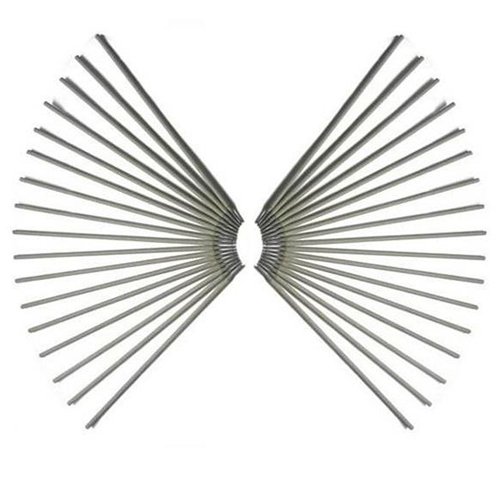
ícel-70|80|90|100|110|120G are high cellulose sodium general low alloy steel electrodes intended for pipe welding, classified under the “G”, viz. general classification. It is general because not all the requirements specified for each of the other classifications are specified for this classification. The intent, in establishing this classification, is to provide a means by which filler metals that differ in one respect or another (chemical composition, for example) from all other classifications (meaning that the composition of the filler metal—in the case of the example—does not meet the composition specified for any of the classifications in the specification) can still be classified according to the specification. The purpose is to allow useful filler metal, one that otherwise would have to await a revision of the specification, to be classified immediately, under the existing specification. This means, then, that two filler metals, each bearing the same “G” classification, may be quite different in some certain respect (chemical composition, again, for example). These electrodes may be either modifications of other discrete classifications or totally new classifications. Purchaser and user should determine from us as to what the description and intended use of the electrode is.
The individual electrodes classified under this electrode group have been designed to match the mechanical properties of the low- alloy steels, such as ASTM API 5L X pipe steel (Grade shall be appropriate for electrode classification strength level).
Storage and Drying Conditions: Not recommended | Ambient temperature (For R-Class)
Cellulosic coverings for this classification need moisture levels of approximately 3% to 7% for proper operation. Therefore, storage or conditioning above ambient temperature may dry these electrodes too much and adversely affect their operation.
Holding Ovens: Not recommended Drying Conditions: Not recommended.
CHEMICAL COMPOSITION OF UNDILUTED WELD
|
C |
Mn | Si | P | S | Ni | Cr | Mo |
Additional Elements |
|
NS |
1.00 | 0.80 | 0.03 | 0.03 | 0.50 | 0.30 | 0.20 |
V=0.10, Cu=0.20 |
Single values are minimal.
To meet the alloy requirements of the “G” group, the undiluted weld metal shall have the minimum of at least one of the elements listed in this table. Additional chemical requirements may be agreed between the purchaser and METAFIL.
ALL-WELD-METAL MECHANICAL PROPERTIES (AW or PWHT)
Preheat and Interpass: NS°C | Post weld Heat Treatment : NS°C for NS Hour(s). The need for, and specific values for preheat and interpass temperatures, and post weld heat treatment
conditions of weld test assemblies made with “G” electrodes shall be as agreed between the purchaser and METAFIL.
|
Class |
Tensile Strength, MPa | Yield Strength, At 0.2%
Offset, MPa |
Elongation % |
Charpy V-Notch Impact at NS°C, Joules |
|
E7010-G |
490 | 390 | 22 | NS |
| E8010-G | 550 | 460 | 19 |
NS |
|
E9010-G |
620 | 530 | 17 | NS |
| E10010-G | 690 | 600 | 16 |
NS |
|
E11010-G |
760 | 670 | 15 | NS |
| E12010-G | 830 | 740 | 14 |
NS |
Single values are minimal.
Impact test specimens are tested without thermal treatment.
Limit of Moisture Content, % by weight max: NS (Reconditioned) | NS (As Exposed) for H4 version Diffusible Hydrogen Content Average, Maximum, mL (H2)/100 g Deposited Metal: NS
Welding Considerations
Preheat and interpass minimum temperatures also have a significant effect on the strength levels attained with certain low-alloy steel weld metals. These weld metals are affected by rapid cooling rates which tend to produce more martensitic or bainitic microstructures. These microstructures will often exhibit higher yield and tensile strengths with a decrease in ductility.
The cooling rate can be retarded by utilizing a higher preheat and interpass temperature. The preheat and interpass temperature ranges given herein are adequate for the preparation of test assemblies.
However, in actual production, users are encouraged to test their own procedures to verify that they have selected preheat and interpass temperatures which will produce desirable results in production.
SIZES & CURRENT CONDITIONS (DCEP)
|
DIAMETER, mm |
LENGTH, mm |
Amperes |
|
2.50 |
350 | 40-80 |
| 3.15, 3.20 | 350 |
75-125 |
|
4.00 |
350 | 110-170 |
| 5.00 | 350 |
140-215 |
WARNING: Safety and health information is available from many sources, including, but not limited to Safety and Health Fact Sheets listed in A11.3, ANSI Z49.1 Safety in Welding, Cutting, and Allied Processes published by the American Welding Society, 8669 Doral Blvd., Suite 130, Doral, FL 33166., and applicable federal and state regulations. The Safety and Health Fact Sheets are revised, and additional sheets added periodically.

